1) Start with the right bearing family and grade
“Oilless” covers multiple technologies, each with different ceilings for load, speed, and temperature.
- Sintered metal (oil-impregnated) sleeves: good for moderate P and V, quiet, economical.
- PTFE- or PEEK-based polymer composites: strong chemical resistance, low friction at low speeds, tolerant of start–stop.
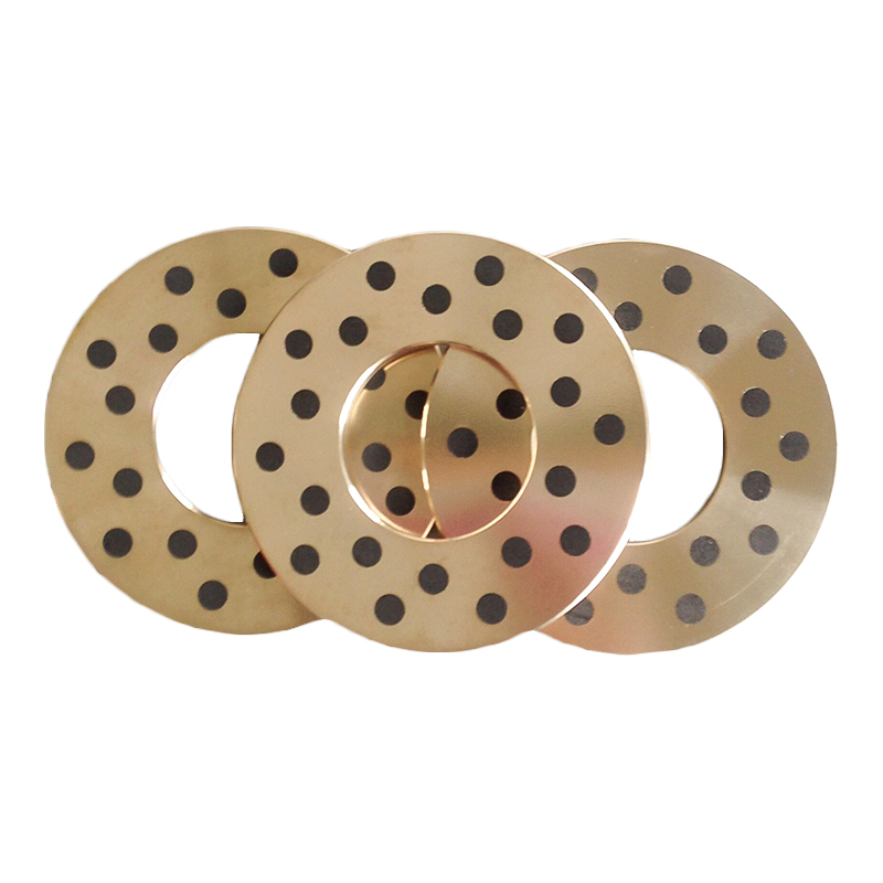
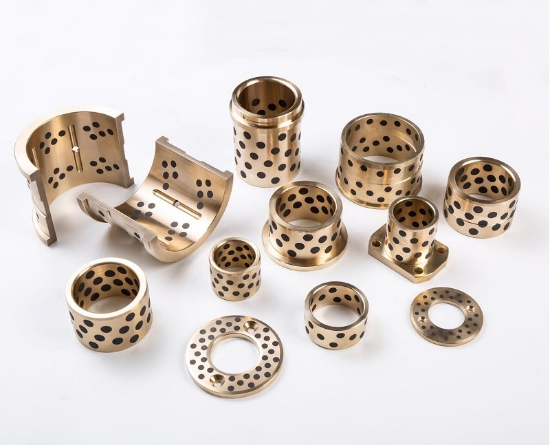
- Bronze or steel with solid lubricant plugs (e.g., graphite, MoS₂): high load, intermittent motion, dirty environments.
- Fiber-reinforced laminates: good stiffness-to-weight, stable over wider temperatures.
Pick the family that matches your dominant stressor (high temperature, shock load, wash-down chemicals, abrasive dust, etc.). This single choice removes many “limitations” before you begin.
2) Design to the PV limit with headroom
The classic constraint is the PV limit (pressure × surface velocity). Calculate both conservatively and design with margin.
- Contact pressure P ≈ Load / (projected area) = W / (d × L) for a sleeve bearing of diameter d and length L.
- Surface velocity V = π × d × n, with n in rev/s (or use belt/linear speed for sliding ways).
Actions:
- Lengthen L or increase d to reduce P, balancing against space and shaft deflection.
- Reduce speed or duty at elevated temperature where PV capacity drops.
- Apply a design factor (commonly 0.3–0.6 of catalog PV limit) to accommodate misalignment, thermal growth, and contamination.
3) Control frictional heat: geometry, materials, and heat paths
Thermal rise accelerates wear and softens polymer matrices.
- Spread the load: longer bearings, or split the load across multiple bearings. Two shorter bearings with a spacing of ≥ the shaft diameter often run cooler than one long bearing.
- Add heat paths: choose housings with higher thermal conductivity (aluminum over plastic), add ribs or a simple finned boss, and avoid insulating paint on the bearing pocket.
- Prefer backing metals with good conductivity for plug-lubricated types; choose polymer grades with higher Tg for hot zones.
- For continuous rotation, consider a shallow spiral micro-groove to distribute solid lubricant and air, but avoid deep grooves that cut load area.
4) Tolerances, fits, and support to prevent edge loading
Edge loading is a leading cause of premature wear in dry bearings.
- Housing bore: roundness and straightness matter as much as nominal size. Use a true cylindrical pocket; avoid ovality from thin-wall housings.
- Fits: typical press fits are light (e.g., H7 housing/p6 bearing for metal-backed bushes); verify vendor recommendations for your material. Too much crush distorts the ID.
- Chamfers and lead-ins: add 30–45° lead-ins on the housing and bearing OD to prevent shaving the bearing during press.
- Shaft support: keep overhangs short; aim for bearing span that limits shaft bending under peak load. A common starting point is spacing equal to 1–1.5× the shaft diameter.
5) Shaft finish, hardness, and roundness
Dry bearings survive on a stable counterface.
- Hardness: for metal shafts, ≥ HRC 50 in abrasive service; in cleaner service HRC 35–45 can suffice for polymers.
- Finish: Ra 0.2–0.8 μm is a practical window. Too smooth can starve transfer-film formation in some PTFE grades; too rough accelerates wear.
- Roundness/runout: hold within 5–10 μm for small diameters where precision matters; verify under operating temperature to account for growth.

6) Misalignment and assembly compliance
Dry bearings dislike angular misalignment because contact concentrates at the edges.
- Use spherical plain bearings or spherical-OD bushings in misaligned linkages.
- If fixed bushings are necessary, add a compliant feature: split housings, thin-wall bushings, or a polymer intermediate sleeve can accommodate small angular errors.
- Provide assembly datum surfaces and gauges that make coaxiality repeatable; misalignment introduced at assembly often dwarfs machining error.
7) Contamination management
Abrasive particles erase the advantage of “no oil”.
- Seal at the system level: simple contact seals, bellows, or felt rings dramatically lengthen life.
- For dusty service, choose plug-lubricated bronze/steel; for wet caustic service, select filled PTFE composites that do not swell.
- Add wipers and debris gutters. Even a shallow relief groove ahead of the loaded zone can trap fines.
8) Motion profile strategies
Start–stop, oscillation, and micro-motions are where oilless bearings shine—if matched correctly.
- Oscillatory motion: PTFE and plug-lubricated types maintain film better than sintered bronze at very small amplitudes.
- Long dwell under load: use materials with creep resistance (PEEK composites, metal-backed PTFE). Increase bearing length to lower contact stress.
- Shock loads: metal-backed bushes with solid lubricant tolerate impact better than unfilled polymers; add mechanical stops so peak impulse bypasses the bearing.
9) Temperature and environment allowances
Dry bearings are sensitive to temperature-dependent modulus and lubricant phase changes.
- Derate PV with temperature according to supplier curves; apply the hot-case first in your worst-case stack-up.
- For wash-down or vacuum: avoid oil-impregnated types that rely on vapor pressure; prefer solid-lubricant or PTFE-filled composites.
- Moisture: some polymers absorb water and swell; allocate radial clearance accordingly and pick low-absorption grades for humid service.
10) Clearance design and running-in
Correct initial clearance allows the transfer film to form without seizure.
- Radial clearance: target the supplier’s recommended range at operating temperature, not at room temperature. Calculate thermal growth of shaft and bearing ID.
- Break-in: plan a short run at reduced load/speed to generate a stable transfer film on the shaft for PTFE-based bearings.
- Avoid pre-lubing with grease unless the manufacturer advises it; some greases hinder transfer-film formation.
11) Layout choices that share load and prevent migration
- Use thrust washers or flanged bushings to carry axial loads; do not rely on sleeve edges alone.
- Stop collars and shoulders: place them to keep the loaded zone centered in the bearing length, not jammed at an edge.
- If axial float is required, provide polished thrust faces and select materials rated for combined radial/axial sliding.
12) Installation practices that protect the liner
- Press only on the bearing’s rigid outer shell; never on the thin liner.
- Keep the bearing and housing dry and free from sealants during press; chemical attack during cure can soften some liners.
- Verify ID after press with a go/no-go plug or air gauge; thin-wall bushings can ovalize.
13) Diagnostics and design feedback
Set up ways to learn from first articles and early field units.
- Measure temperature rise at steady state; excessive rise signals PV overload or misalignment.
- Track current draw in motorized systems; a gradual increase indicates rising friction.
- Inspect wear patterns on returned parts: uniform gray transfer film is healthy; shiny edges or streaks indicate edge loading; embedded grit indicates sealing gaps.
14) When limited lubrication makes sense
“Oilless” does not forbid all lubrication; in tough duty a tiny assist can unlock life.
- Dry film coatings on the shaft (MoS₂, DLC) reduce break-in wear.
- A sparse, compatible paste during commissioning can establish the film, then run dry.
- If you must add grease periodically, choose one that does not attack the liner and apply very small amounts to avoid attracting grit.
15) Cost-aware robustness
Many improvements are geometry or process choices rather than expensive materials:
- Two shorter bushings with a spacer often outperform one long bushing at similar cost.
- A better shaft finish and a dust wiper are often more impactful than a premium bearing grade.
- An aluminum housing boss that thickens the pocket and adds a simple fin reduces distortion and heat with minimal tooling change.
Quick selection checklist
- Identify the dominant stressor: heat, dust, chemicals, shock, or continuous speed.
- Choose the bearing family whose intrinsic limits align with that stressor.
- Size on PV with margin; adjust diameter/length and duty to stay well below the limit at the hot case.
- Engineer the interfaces: shaft hardness/finish, housing tolerance, alignment strategy, sealing.
- Validate with instrumented tests; read wear patterns and iterate.
Apply these steps and you convert typical “limitations” of oilless bearings—PV ceiling, heat buildup, edge wear, sensitivity to contamination—into manageable design constraints. If you want, tell me your load, speed, temperature, and environment, and I’ll size a bearing, pick a material family, and draft tolerance notes you can drop on a drawing.


 English
 Español


 Tel: +86-136-6679-1592
 E-mail: [email protected]


Contact Us