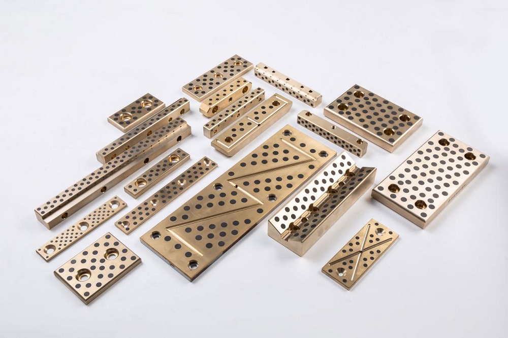
In the precision transmission of mechanical equipment, copper plate bushings play a pivotal role. They not only guide motion but also transmit loads. However, they often become the “short-lived components” in equipment due to severe wear caused by looseness or deformation and cracking resulting from excessive tightness. How can this problem be solved? Scientifically calculating and controlling the interference fit is the core method for extending the service life of copper plate bushings.
I. Lifespan Killers: The Double Trap of Improper Interference Fit
The failure of copper bushings often stems from an imbalance in interference fit:
1. Insufficient Interference Fit (Too Loose)
- Symptoms: Micro-sliding occurs between the bushing and the base hole.
- Consequences: Micro-sliding wear accelerates rapidly, generating wear debris that damages the mating surfaces. This ultimately leads to bushing looseness, abnormal noise, inaccurate positioning, and a significant reduction in lifespan.
2. Excessive Interference Fit (Too Tight)
Conclusion: The key to extending lifespan lies in finding a “golden interference fit range”—one that provides sufficient bonding force to eliminate micro-sliding wear without generating destructive high stresses.
II. Finding the “Golden Range”: The Five-Step Scientific Calculation Method
Step 1: Identify the “Enemy” — Workload Analysis
- Clarify the tasks: Determine the maximum torque the bushing needs to resist, as well as the magnitude of axial or radial forces it will bear.
- Consider the environment: Assess whether there is strong vibration or impact, and determine the operating temperature range (temperature affects expansion).
- Understand the load nature: Determine whether the load is a steady static load or a repeatedly applied fatigue load. Dynamic loads require a larger safety margin.
Step 2: Calculate the “Minimum Defense Line” — Minimum Required Contact Pressure (P_min)
- Objective: Ensure that there is absolutely no relative sliding between the bushing and the base hole under working loads (eliminating micro-sliding wear).
- Core formula (for torque transmission T):
P_min = μ × (π × D² × L / 2) × T × S_f
Where:
-
T = Maximum working torque (N·mm)
-
S_f = Safety factor (usually 1.5–3.0; higher for vibration and impact)
-
μ = Static friction coefficient between the copper bushing and the steel/iron base (typical 0.1–0.2)
-
D = Fit diameter (nominal, mm)
-
L = Fit length (mm)
-
Even without external loads, a basic pressure of 5–15 MPa should be maintained to prevent micro-sliding.
Step 3: Define the “Safety Red Line” — Maximum Allowable Contact Pressure (P_max)
- Objective: Ensure that the copper bushing does not undergo yield deformation or crushing failure.
- Simplified calculation:
P_max ≈ S_y × σ_yield
Where:
-
S_y = Yield safety factor (1.2–1.5)
-
σ_yield = Yield strength of the copper bushing material
-
Precise calculation using thick-walled cylinder theory:
P_max = 3 × σ_yield × [1 – (d_i / D)^4]
Where:
-
d_i = Inner diameter of the copper bushing (mm)
-
D = Outer diameter of the bushing/base hole diameter (fit diameter, mm)
-
Important: Check whether the stress in the base (cast iron, aluminum, etc.) hole wall exceeds allowable limits.
Step 4: Convert “Pressure Metrics” — Theoretical Interference Fit Range (δ_min_th, δ_max_th)
- Objective: Convert pressure requirements into specific diameter interference fit values.
- Core formula:
δ = P × D × (K_cu + K_h)
Where:
-
K_cu = (E_cu / (Do_cu² – D²)) × [Do_cu² + D² + ν_cu] (parameters for the copper bushing)
-
K_h = (E_h / (D² – Di_h²)) × [D² + Di_h² – ν_h] (parameters for the base)
-
E_cu, E_h = Elastic modulus of copper and base (copper ~110 GPa, steel ~210 GPa)
-
ν_cu, ν_h = Poisson’s ratios (copper ~0.34, steel ~0.3)
-
Do_cu = Outer diameter of the copper bushing (=D)
-
Di_h = Inner diameter of the base hole (0 for solid base)
-
Substitute P_min to obtain δ_min_th
-
Substitute P_max_allowable / S_y to obtain δ_max_th
Step 5: Correct for “Real-World Losses” — Design Interference Fit Range (δ_min_design, δ_max_design)
- Surface roughness: Peaks on the surfaces flatten during press fitting, consuming part of the interference fit.
δ_eff ≈ δ_design – 0.8 × (Rz_cu + Rz_h)
-
Rz_cu, Rz_h = Ten-point height of surface irregularities of the bushing and base hole (μm).
-
Temperature-difference assembly (shrink/expansion fitting) avoids flattening loss.
-
Corrected design values:
- δ_min_design = δ_min_th + δ_loss (ensuring actual effect ≥ δ_min_th)
- δ_max_design = δ_max_th + δ_loss (but verify P ≤ P_max_allowable)
-
Temperature compensation: Calculate Δδ caused by thermal expansion/contraction to ensure:
- δ_eff_working > 0 (no looseness)
- Corresponding pressure ≤ P_max_allowable (no cracking)
III. Practical Tips for Maximizing Lifespan
1. Doctrine of the Mean
- Optimal design interference fit usually lies at 60–75% of δ_max_design, providing safety margins while avoiding stress limits.
2. Tolerance — Lifeline of Precision
- Achieve design values through strict tolerances (common fit grades: H7/s6, H7/u6).
3. Surface Finish
- Reduce roughness (Ra ≤ 1.6 μm) on both bushing and base hole to minimize press-fitting losses and improve stress uniformity.
4. Assembly Method
-
Press fitting: Requires precise guidance, uniform pressure, lubricant (e.g., molybdenum disulfide paste), and controlled pressing speed.
-
Temperature-difference assembly (recommended):
- Shrink fitting: Heat the base hole.
- Expansion fitting: Cool the copper bushing (e.g., liquid nitrogen).
- Advantages: Uniform stress, minimal assembly damage, precise realization of theoretical interference fit.
5. Strengthening the Bushing
-
Material upgrade: Use high-strength, wear-resistant copper alloys (e.g., aluminum bronze QA110-4-4, tin bronze QSn7-0.2).
-
Structural optimization:
- Increase wall thickness for higher load-bearing capacity.
- Add stress relief slots in non-load-bearing areas to reduce local stress concentration.
6. Lubrication and Maintenance
- Ensure continuous and effective lubrication between the bushing bore and shaft.
- Regularly inspect for abnormal noise, temperature rise, or looseness and address issues promptly.
IV. Conclusion: Balance is the Key
Extending the service life of copper plate bushings is not about “the tighter, the better.” Instead, it involves balancing: tight enough to prevent looseness, yet not so tight as to exceed material stress limits. This requires:
- Precise calculation using the five-step method
- Fine correction considering roughness, assembly method, and temperature effects
- Meticulous manufacturing with strict tolerances and surface quality
- Optimal assembly, prioritizing temperature-difference methods
- Optimized material selection and structural design
- Conscientious maintenance with proper lubrication and inspection
For extreme operating conditions or new designs, finite element analysis (FEA) simulations and small-batch physical lifespan tests are essential to verify interference fit design. Combining theory with practice ensures copper plate bushings achieve longer lifespans, enabling smoother and more reliable equipment operation.


 English
 Español


Contact Us