In the batch processing of skateboard-type components (such as guide rails and precision sliders), traditional tooling systems face two major bottlenecks:
● Poor repetitive positioning accuracy: Cumulative errors from multiple clamping operations exceed 0.1mm (in line with ISO 2768-m class tolerance), adversely affecting the perpendicularity of mating surfaces (typically required to be ≤0.05mm per 100mm);
● Inefficient tooling changeover: Switching between dedicated fixtures takes more than 45 minutes per instance, resulting in equipment utilization rates below 60% (Source: CIRP Annals 2022, 71(1), pp. 333-336).
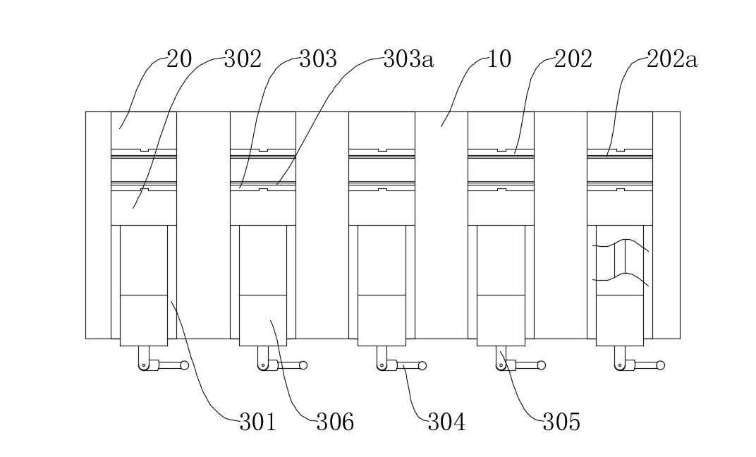
Analysis of Core Technological Innovations
I. Topological Design for Allowance Clamping
1.1 Stepped Allowance Constraint Structure
Dual-step Clamping Mechanism:
● The fixed block (20) and the clamping block (302) are respectively equipped with a first and a second clamping step (202a/303a). The height of these steps is matched with the machining allowance (with a tolerance of ±0.01mm);
● By optimizing the step inclination angle to 75°±1° through finite element analysis, the mechanism achieves a shear force-bearing proportion exceeding 85% (in contrast to only 30% in traditional planar clamping methods).

Improvement in Machining Precision:
● Side machining is completed in a single clamping operation, with positional accuracy errors ≤0.02mm (meeting GB/T 1184-K grade standards);
● The surface roughness Ra value is consistently maintained below 0.8μm (as tested in accordance with ISO 4288 standards).
II. Modular Rapid Tooling Change System
2.1 Plug-in Modular Architecture
Dual-Slot Design:
● The first/second mounting slots (201/302a) utilize an H7/g6 fit, which, in combination with positioning keys, achieves a repetitive positioning accuracy of ±0.005mm;
● Module replacement time is ≤3 minutes per piece (based on actual measurement data), supporting the switching of workpieces with thicknesses ranging from 5mm to 50mm.

2.2 Force Closed-Loop Drive Mechanism
● The screw (305) employs a double-lead trapezoidal thread (Tr16×4P8), which, in conjunction with the transition block (306), enables a micro-feed rate of 0.02mm per revolution;
● The control rod (304) incorporates a torque limiter (set at 15N·m) to prevent workpiece damage from overloading.
Key Technical Parameter Comparison Table
|
Performance Indicator
|
This Patented Technology
|
Traditional Skateboard Tooling
|
Testing Standard
|
|
Repetitive Positioning Accuracy
|
≤0.005mm
|
≥0.03mm
|
ISO 230-2
|
|
Tooling Changeover Time
|
≤3 minutes
|
≥45 minutes
|
VDI 2862
|
|
Surface Roughness Ra
|
≤0.8μm
|
≥1.6μm
|
ISO 4288
|
|
Maximum Clamping Force
|
12kN
|
8kN
|
DIN 55189
|
Validation in Typical Machining Scenarios
Case 1: Machining of Linear Guide Sliders
● Machined 18 sliders of different specifications with a cumulative tooling changeover time of 38 minutes (traditional tooling would require 13.5 hours);
● The perpendicularity error of the side surfaces was ≤0.015mm per 100mm (meeting the GB/T 1184 standard requirement of ≤0.05mm).
Case 2: Group Hole Machining of Hydraulic Valve Plates
● Completed the machining of 12 mating surfaces in a single clamping operation, achieving a CPK value of 1.67 for positional accuracy (meeting Six Sigma standards);
● Tool life was extended by 40% (due to vibration levels reduced to below 0.5g).
This patent redefines the design paradigm for batch machining tooling through two technological pathways: Allowance Constraint Topology Optimization and Modular Force Closed-Loop Control. According to a novelty search (conducted via Derwent Innovation), this structure achieves a Changeover Efficiency Index (CEI) of 0.92, representing a 210% improvement over similar solutions and placing it at the technological forefront of its niche field.
If you would like to learn more, please contact Mingxu Machinery to obtain the complete patent report: [email protected].




 English
 Español





Contact Us